latest news

ICR/ICRm wagons now for sale.
![[menu logo]](../images/christrainslogodot.png)
ICR/ICRm wagons now for sale.
Want to start or grow your collection by more than one product? Use these coupon codes for bulk discounts:
GIMME2 = 10% off two products
GIMME3 = 15% off three products
GIMME4 = 20% off four or more products
Subscribe to the mailing list for occasional updates and important announcements.


This is the legacy (pre-October 2017) version of the coupling calculator. A newer DTG-recommended calculation can be found at this link. NOTE: Do not mix wagons calculated with the legacy version, with those calculated with the DTG-recommended version. They will work ok but when coupling, the wagons could pass through each other by about 20cm
Unlike commercial simulations, the coordinate system in Train Simulator is a screenspace XYZ coordinate system instead of a worldspace one. In worldspace, XY is the ground and Z is up. In screenspace, XZ is the ground and Y is up. So for a wagon or engine, this is the working coordinate system:

Positive X is across the wagon, to the right. Negative X is left. Positive Z is forwards, negative Z is backwards, and positive Y is upwards.
Through trial and error, I've come up with a good way to get the pivot points and collision boxes to work consistently in Train Simulator. I'm not saying this is the 100% correct way to do it, but this method does work reliably.
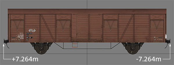
First - ensure your wagon is centred around the zero point of the model so that the furthest points front and rear are at the same Z coordinate. For a freight wagon like this, this would normally be the tips of the buffers:
Once you know the coordinate value of the tips of the buffers, put those numbers into this little javascript calculator, along with the overall height and width of the wagon, and it will show you the relevant values to put into the blueprint editor:
Note: The blueprint editor has typos in it for the pivot points. Front pivot X should read Front Pivot Z and Back pivot X should read Back pivot Z.
Front pivot Y and Back pivot Y are the midpoint of the buffers off the ground. These can normally be zero as the game doesn't seem to care much about them.
This picture sums up all those values:

Really important note about the height: The calculator above will give you a collision height and centrepoint - it's really important you enter the correct height before using it. Train Simulator has an interesting quirk with regards to the collision height; if that imaginary white box in the picture above dips below the ground at any point, it makes it impossible to actually get near the wagon in the game - engines and other wagons will bounce off it about 6-10m in front of the wagon itself. I have no idea why this is, but my calculator figures out the correct height for the centrepoint by halving the value you enter for the overall height, then adding 10cm just to be absolutely sure the box never dips below the ground. So if you try to couple to your wagon and the engine bounces off an invisible box 10m from it, you know why now.
When I'm talking about chain couplings, I'm making a couple of assumptions, shown below. The hooks are built as part of your wagon or locomotive, and your coupler has three different components - a 'coupled' model, an 'uncoupled' model and a 'receiver' model. Each of these models must be built at the origin (0,0,0):

Assuming you are using a 3-link / chain type coupling, the pivot points for this type of coupling look like this. The blue wireframe shows the buffers at one end of the example wagon, the white wireframe is the hook model:

The values below should have been filled out when you calculated the collision and pivot information above. Note that the Y value is something you need to measure off your model - the height of the coupling off the ground.
Solid couplings work a little differently to chain couplings. The geometry for the coupling is built in two pieces - a coupled and an uncoupled version. The uncoupled version is built around the origin (0,0,0) facing forwards (positive Z). This allows the coupler to be placed somewhere on the wagon, facing outwards. The coupled version is more or less the exact same geometry but rotated around 180° so that the coupling face is now at the origin point:
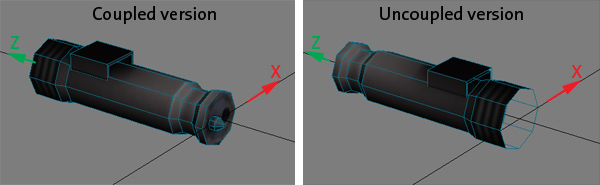
Solid couplings typically extend a little bit beyond the tips of the buffers. I've found about a centimetre works well - 0.012m. You also need to know the length of the solid coupler - measure that from your model. In this example it's 0.91m. So the receiving point is a little ahead of the buffers, and the pivot point is that value minus the length of the coupling model itself:

Use this little script to figure out the solid coupling pivot and receiving points based on the tips of the buffers in your wagon:
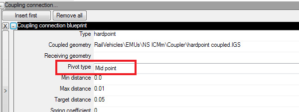
The last thing you need to do for a solid connection is make sure your coupling blueprint has the Pivot Type set to Midpoint
At this time I have not had a chance to research an easy formula for the pivot points for buckeye couplings.
As I said above, this might not the most technically correct way to get these numbers but it's worked perfectly for me for dozens of wagons and engines. I hope it works for you too.
![[email]](../images/email-blue.png)


 is the property and trademark of Nederlandse Spoorwegen.